 1986-88 AMPLIFIER, low freq audio (UQ6) 16040752 $41.15
1986-88 GASKET, speaker, subwoofer 16042197 $1.15
1986-88 GRILLE, subwoofer 16042199 $3.95
1986-88 HOUSING, subwoofer 16029862 $117.00
1986-88 SPEAKER, subwoofer 16041072 $27.50
1986-88 HARNESS, amp wiring 12046518 $62.25
1986-88 HARNESS, reading lamp & subwoofer 20521747 N.L.
LAMP, reading & dome, w/UQ6
1986-88 DK gray 20636322 $62.50
1986-87 DK Saddle 20636323 $62.50
1988 Med Beechwood 10076175 $62.50
From: Scott Backer
Installation and Removal
Installation - all models
These instructions are for installing a factory Fiero subwoofer onto any
Fiero, regardless of the year, or option package. This installation method
duplicates the factory installation, including the routing of the wiring
harness.
You can SHORTCUT this procedure by skipping past the removal of the main
instrument pod and main dash board. All the rest of this procedure is the same.
The only difference between the two installations is that the SHORTCUT will have
the wires routed across the steering column by fishing them between
instrumentation frame work, rather than sharing the wire harness hold-down clips
in that area.
Allow a day for this task, or 3 to 5 hours if you use the SHORTCUT method.
Tools required are simple screw drivers, socket wrenches, pliers, putty knife,
and a T15 and T45 torx driver. Installation is based upon a complete car with
the interior and windshield in place. This is a one man/woman job, as there is
no need for assistance.
Glancing at this article may scare you based on it's length. But it is not
hard to do for someone with minimal automotive "Hands On" experience. The
article is just Very descriptive.
Additional Recommended Upgrading
This job provides a good opportunity to upgrade the original 4x10 10 ohm dash
board speakers along with the sail panel speakers (if equipped), with good
quality 2 or 3-way, 4 ohm speakers. I also recommend installing "Good Grade"
carpet padding as a speaker enclosure behind the front speakers to enhance their
sound quality, as well as muffle the subwoofer's air burst noise. Get these
items prior to starting the project.
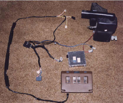
Subwoofer Components
- Subwoofer speaker in housing including
2-wire connector
Right angle
vent tube
2 mounting screws with 7mm heads
- Amplifier and mounting screw with 7mm head
- Courtesy light with slide control for subwoofer (reuse old screws)
includes a 4-wire connector
- Wiring harness which consists of two sections, which are likely to be
connected together as one unit. Description is as follows.
- First, main harness section consists of
Milti-wire for radio
connection
Milti-wire for original radio wire harness
connection
Milti-wire for amplifier
2-wire yellow and white for
connection to 2nd harness
2-wire black and blue for subwoofer
connection
Screw with 7mm head for mounting harness to chassis behind radio
- Second harness section consists of 4-wire connector for courtesy light -
orange, yellow, two white wires
2-wire orange and white for courtesy light
power distribution block
2-wire yellow and white for connection to 1st
harness
Old Components That Will "No Longer" Be Needed
- Original courtesy light housing with 2-wire connector
- 2-wire harness that powers up the courtesy light
The Procedure
The very first thing to do is...
Disconnect the battery, because you will be handling a number of
electrical connections, some of which will have power. Remember that
all connectors have locking features to prevent unwarranted
removal, so do not force a disconnect. Lift or squeeze the locking
taps, for proper disconnect. Always pull on the connectors, and not their wires.
Study each connector carefully.
Main Instrument Pod Removal (If Using The "Complete" Method Only)
- Remove the lower pod cover - 4 7mm screws (under steering column)
- Remove upper/back pod cover - 5 T15 torx screws top, 2-7mm bottom
- Remove the headlight control panel - 4 T15 torx screws and 2 connectors
- Remove the trunk release and defroster panel if equipped - 4 T15 torx
screws and 2 connectors
- Remove 2 black plastic wire harness clips (horseshoe shape)
- Pop off metal wire harness clip for light connectors (left side)
- Pop off metal wire harness clip for trunk/defrost connectors (right side)
- Pry off 2 clear plastic wire harness clips on the lower section of pod
- Remove 3 multi-pin pod connectors
One is left side/back
One is right
side/back
One is left side bottom
- Remove 2-10mm screws on pod top, and 2-10mm screws on pod bottom
- Slowly lift and remove pod assembly
Center Console Removal (From The Shifter Forward)
- Remove shift knob
Unscrew knob for stick shifts
Remove the clip in
the front of the knob for the automatic, then lift
- Remove shifter cover - 4 7mm screws under ash trays
- Slowly lift and remove cover
Disconnect indicator light connector for
automatics
- Remove radio cover plate - 4 T15 torx screws
It has a snap feature so
pull away carefully from the middle
- Remove radio - 4 7mm screws
Disconnect the radio multi-pin
connector
Disconnect the radio antenna
Disconnect the 2-wire radio light
connector
- Remove vinyl radio/heater control pod cover - 5 7mm screws
- Remove secondary instrument pod if equipped
Cover plate - 4 T15 torx
screws
Instrument pod - 4 7mm screws in the lower metal piece
Disconnect
electrical connector
- Remove metal console reinforcement plate - 4 or 6 7mm screws
Main Dash Board Removal (If Using The "Complete" Method Only)
- Pop off the dash speaker grills using a flexible putty knife. Be careful
not to lift one side too high, until the other side has lifted a little, to
prevent breakage. Using a screwdriver or other narrow bladed tool could ruin
the dash board by applying too much pressure in a concentrated spot.
- Remove speaker screws - 8 7mm
- Lift, disconnect, and remove speakers
- Remove the 2 pairs of 7mm screws that are located by each speaker hole.
These are screwed horizontally towards the windshield.
- Remove the 2 10mm screws located at each lower end of dashboard below each
side vent.
- Remove the 3 phillips screws that attach the hood release lever assembly
to the dash board.
- The dash is held in by the 4 top 7mm screws and the 2 bottom 10mm screws,
along with 2 tabs from the center console's black plastic skeletal structure.
After removal of the 6 screws, carefully separate the 2 tabs of the center
console from the dash. Then work the secondary instrument pod's wire harness
out the hole of the dash, if equipped. Then carefully lift and remove the dash
board out of the car.
- There are no wires or ducts to worry about, other than the
connection to the secondary instrument pod, if so equipped. The dash is very
light, so no help is needed.
Time For Detailing
Take this opportunity to clean up all the interior components of the car. A
smoker's car could certainly use a good cleaning. The results will make the
interior look almost new.
Headliner's Courtesy Light, Sail Panel, And Associated Wire Harness
Removal
- Remove the driver's side sun visor by removing the 3 phillips screws.
- Using a small screwdriver, pop off the 2 outer light lenses in the old
courtesy light housing. Remove the 2 chrome T15 torx screws. Remove the 2
remaining T15 torx screws in the courtesy light housing located where the 2
sun visors snap in. Disconnect the 2-wire connector and remove the housing.
- Remove the upper seat belt hoop, by popping off the plastic cover, and
then using the T45 torx driver for disassembly.
- Remove the driver's side rear speaker sail panel by first removing the
visible phillips screw on the side where the door closes. Then place a LARGE
screw driver above the screw hole by about 10 inches and pop out the fastener
in the direction from rear to front of car. Then simply work the panel away
from the wall. The only attachments are the screw, the one fastener, and the
top seat belt bolt. The rest is held in by fit. With the sail panel removed,
you can see that the speaker grill is not removable from the panel, as it is
held in with hot melt pins. These pins are a little loose, so it is good to
apply a dab of RTV on each pin to prevent vibration from the speaker's sound.
This is a good time to replace those old rear speakers with some better ones.
Of course you would have to do the passenger side of the car in the same
manner.
- Remove the driver's side door pillar trim. My opinion is that this is the
trickiest part of the whole job. This long piece is held in 4 places using 2
types of fasteners. It is important to follow this procedure due to it's ease
of destruction. First detach the area that is across the top of the side
window by placing a putty knife from the outside-in, between the trim
and the "car frame" and separate. During separation, look for the 2 plastic
molded tabs from the trim to metal clips. It is there where the putty knife
should be located during separation. It should take some force, but not too
much. Afterwards the 2 remaining fasteners in the windshield area must be
simply popped off by carefully tugging on the trim, away from the pillar. Do
not pull the trim so hard as to break it. You could encourage separation with
a long screw driver inserted behind the trim. Do not let the
screwdriver make contact with the windshield. After separation, the 2 white
clips will be stuck in the pillar. Use a small screwdriver to move the center
tab of each clip away from the pillar's slot to easily lift the tab
out of the pillar. Forceful removal will break the clip, making it
unusable. Then reattach the two clips on the trim for reattachment
latter.
- Now that the trim is removed, pull the headliner down just far enough to
access the old wire harness. Pop out the wire harness clips from the roof, and
work the wires out the wire channel along the windshield. disconnect it at the
white plastic power distribution block located in the far front corner. Make
note of which position it plugged into so you know where to plug the new one
in.
Installing The New Wire Harness
Position the new harness behind the radio cavity. The black boxed connector
plugs into the old radio connector, and then gets screwed to the car frame by
the provided plastic flap with hole. A predrilled hole in the car frame is also
provided. The duplicate connector will plug into the radio latter. The smaller
multi-pin connector must be worked behind and down to the passenger floor. The
blue and black 2-wire goes to the subwoofer above the passenger's feet. A
plastic tab in the heater core housing is for the clip in that harness. The
yellow and white wire pair gets placed across the steering column (sharing the
wire clips) and then up the windshield along with the orange and white wire pair
to the courtesy light. The orange and white wire connector goes to the power
distribution block as previously discussed. Remember all the parts you removed
earlier must be reinstalled, so make sure that the harness will not get pinched
or twisted during final assembly.
Installing The Subwoofer Enclosure
The subwoofer enclosure is mounted just above the passenger's right foot
vinyl rest. Position the subwoofer such that it's mounting brackets align with
the dash and chime unit brackets. The speaker faces down, and the vent tube is
up and to the driver. The chime and dash brackets have predrilled holes
dedicated for the screws of the subwoofer. Complete the wire harness
connection.
If you are following the SHORTCUT method with the dash and main instrument
pod in place, working the subwoofer into position is much easier with the
passenger side dash speaker removed. This will allow you to get your hand in
there to help position the housing properly. See dashboard removal section on
how to remove this speaker.
Installing The Amplifier
Remove the carpet clips on the passenger side console, and pull the carpet
back. Identify and remove the 4 black retainer buttons for the large black
plastic side cavity. It measures roughly 2 feet long by 10 inches high by 2
inches thick. It has a number of bends in the top to follow the center console's
shape. Pull this piece out and mount the amplifier in it with a 7mm screw.
Reposition it back, and attach the small multi-pin connector to it. Keep in mind
that the harness must not get pinched or twisted, but rather lay nicely from the
radio to the black plastic side cavity, with no interference to the missing
console pieces yet to be installed. Reassemble this cavity and carpet to the
car.
Installing The Courtesy Unit, And Then Test The Subwoofer
Plug the courtesy unit with the subwoofer slide control, into the 4-pin
connector, and mount to the roof. Double check all subwoofer connections, and
then plug in the radio, and antenna, along with the two dash speakers. Again,
make sure all cables are laid and held down properly. With all other instruments
and dash still removed, make sure their connectors are not touching metal. Then
connect the car battery and power up the radio by turning the ignition key to
accessory. Test the functionality of the subwoofer. Assuming you did everything
right and you have a good subwoofer unit, it should work.
Disconnect the car battery once again, and then reinstall the balance of
components in the reverse order of disassembly, making sure that all wires are
secured the way the factory did it, and watch out for wire pinching and
twisting. Don't forget the upgraded speakers and carpet padding too. |